Table of contents
- Overview
- Frontpanel layout
- Functional description
- Connectors on the back
- Technical details
- Installation
- More information
- Warranty
Overview
Congratulations to the purchase of SHMIX and welcome to the world of manikk!
SHMIX is a 6 channel DC mono mixer with separate input attenuator knobs for each channel. The mix output has a separate master level knob. The mix can also be levelshifted by the shift knob and sent to a separate shift output. All knobs are linear. On the backside there are pin strips for all inputs and outputs. These pins are connected when no cables are attached to the jacks. If you insert a cable in a jack, then the connection to the pin on the backside is broken. This can be used to have the normal functions connected on the backside and hide some cables in the front. You can also chain multiple SHMIXes together with the pins on the backside.Package Contents
- 1 Module
- 2 Screws
- 1 Power cable
- Cardboard box
Pins on the backside
The pin-strip on the backside has a signal-pin and a GND-pin for each function.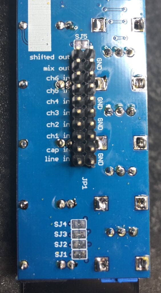
- Shifted out
- Mix out
- Channel 6 input
- Channel 5 input
- Channel 4 input
- Channel 3 input
- Channel 2 input
- Channel 1 input
- Cap input – has a DC blocking capacitor at the input
- Line input – no capacitor, just an additional line in for cascading
Click here to go to the product page.
Frontpanel layout
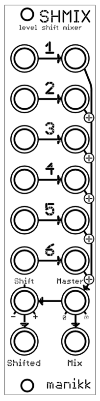
Functional description
Inputs
The mixer has 6 inputs.
Each input can be attenuated by a dedicated attenuator knob.
All knobs are linear.
Outputs
The man level of the mix can be controlled by the “Master” knob and the mixed signal is fed to the Mix jack.
The mixed signal can then be level-shifted with the “Shift” knob and the shifted signal is fed to the Shifted jack.
The knobs are linear.
Connectors on the back
Power connector
The power connector should be connected to the Eurorack power supply bus with the supplied ribbon cable.
Warning! Make sure that the polarization will be correct. The red stripe is -12V and should be oriented to the side indicated on the PCB.
Pin header
All functions have a pair of pins on the backside. If you connect a signal here, it will be fed to the jack without the need to insert the cable on the front. If you insert a cable in the front-jack, it will get higher priority and deselect (break) the signal connected on the backside.
There are two additional pins for chaining two or more mixers together: “cap-in” and “line-in”. They are mixed together to the total mix but do not have any gain knobs. The cap-in signal has a DC-blocking capacitor and the line-in does not have a capacitor.
Warning! Make sure that you orientate your connectors the correct way when connecting to these pins. Ground is marked with GND-texts on the PCB and the other side is the signal pins.
| Pin | Description | Break-jack-function |
| Shifted out | Level shifted signal out | If you insert a cable in the front shifted jack, the signal to the shifted-out pin is broken. |
| Mix out | Mixed signal out | If you insert a cable in the front mix jack, the signal to the mix-out pin is broken. |
| Ch6 in | Channel 6 in | If you insert a cable in the front input 6 jack, the signal from the ch6-in pin is broken. |
| Ch5 in | Channel 5 in | If you insert a cable in the front input 5 jack, the signal from the ch5-in pin is broken. |
| Ch4 in | Channel 4 in | If you insert a cable in the front input 4 jack, the signal from the ch4-in pin is broken. |
| Ch3 in | Channel 3 in | If you insert a cable in the front input 3 jack, the signal from the ch3-in pin is broken. |
| Ch2 in | Channel 2 in | If you insert a cable in the front input 2 jack, the signal from the ch2-in pin is broken. |
| Ch1 in | Channel 1 in | If you insert a cable in the front input 1 jack, the signal from the ch1-in pin is broken. |
| Cap in | Optional DC-blocking input. | No break-jack-function. The signal is fed through a 10uF capacitor and becomes a part of the total mix. |
| Line in | Optional input | No break-jack-function. The signal is fed directly to the input and becomes a part of the total mix. |
Converting to an AC-mixer
On the backside there are 6 small capacitor symbols. Each of these have a copper-wire in the middle that by default connects the two solder pads.
It is possible to cut this little copper wire for each of these 6 capacitor symbols and then solder six 0805 SMD 10uF capacitors there.
If you want to convert it back to a DC mixer again, you have to reverse the procedure by desoldering the caps and solder a new wire for each of the 6 capacitor symbols again.
Beware that this conversion voids your warranty!
Technical details
Dimensions
Width: 6 HPDepth: 21 mm
Current consumption
+12V: 7,5 mA-12V: 7,5 mA
Installation
Installation
If you have purchased a module, you need to install it in your eurorack case. Use the supplied screws to mount it in your rack.
An expander or add-on needs to be attached to the back of a master module via pin-strips. Either directly or via dupont-cables.
Power supply
There are three types of power requirements for manikk products:
- Completely passive products requires no power.
- Normal eurorack modules requires +12V and -12V from your eurorack system. Connect with IDE ribbon cable.
- Some kits and add-ons requires only +5V from a master module. Connect directly or with dupont-cables.
NOTE!
- Make sure to use approved and good power supply in your system.
- Always turn off the power to your system when installing or uninstalling modules.
- Make sure to get the polarization correct when connecting cables.
- When you connect an IDE flat ribbon cable to the eurorack power distribution, the negative -12V is normally indicated with text on the PCB and with a red stripe on the cable.
More information
You can find the latest information on the website www.manikk.com.
- Latest version of this manual
- Additional information
- Videos
- FAQ
- Other modules and kits
Warranty
This device has a one (1) year limited warranty starting from the first purchase date.
The warranty covers malfunctions in the device.
The warranty does not cover bad usage, external damage or other abnormal usage.
The device is designed to work in a Eurorack synthesizer system. Other uses are not covered by the warranty.
If you have to use this warranty you need to do the following:
- Check that the date is still in the warranty-time of 1 year from the date of purchase.
- Contact the seller where you purchased the device.
- Send the malfunctioning device to the address given by the seller. You have to pay for this freight yourself. Very important that you attach your return-address to the device, so we know where to return the repaired device.
- Manikk will repair or replace the device if the problem is covered by the warranty. We will send the repaired device back to you.